Construction Notes North Staffordshire Railway / Isle of Wright Steam Railcar by Kerry Viney |
|
 |
|
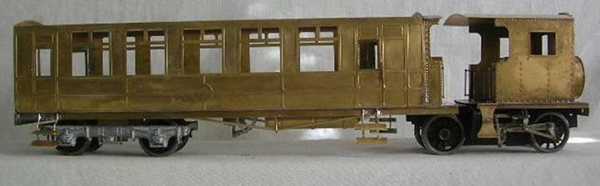
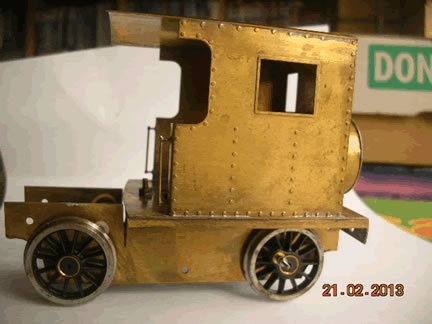
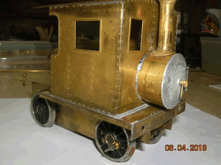
| Several years ago whilst visiting my son and family, I received an invitation from the late Roy Slaymaker to visit his model railway club for their Christmas running day which was held at Sir William McAlpines private railway museum. I had a most memorable day, meeting several 0 gauge scratchbuilders and falling in love with the NSR steam railcar doing the circuit on the club layout inside the museum. I soon had a set of etches from Worsley Works and commenced construction of the body of the loco and passenger section. The photos below show the stages of construction which is straight forward. The roof is sanded to shape from a small wood offcut. The bogie was built up from brass strip and the Mashima motor fitted between the axles. The Walsherts valve gear , at that time, needed more than I was capable of, so the project went to the “Work in Progress” section of the kit cupboard. That is, until this year, with more modelling experience and determation I made a start. Whilst in UK this year I visited David Halliwell, and gained a lot of scratchbuilding knowledge and construction tips. |
|
 |
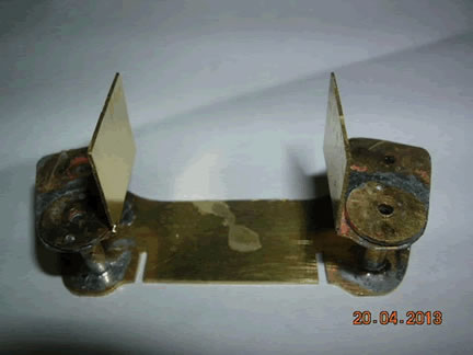 |
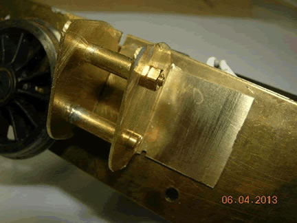
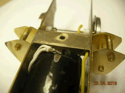
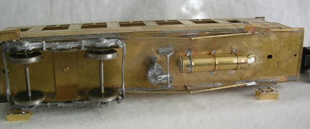
| The first being how to construct the cyclinder unit, see diagrams and reference material above. Tube to take 1.6mm brass rod is used to space the two cyclinder frame pieces 11mm apart. The cyclinder wrapper is a piece of thin brass strip cut to size with rivets punched out using hand pressure on a large steel nail that had the end ground to shape, tinned with standard solder and soldered in place using low melt solder. |
|
 |
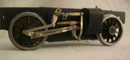 |
Next step was making up the connecting rods using nickel silver strip filed to shape drilled on the small end and fitted to the crosshead with a 12BA bolt and nut, later to be secured with a drop of super glue or nail polish. The crosshead is made by soldering a drilled triangled shaped piece of nickel silver, with 2 holes drilled in it, one for the connecting rod and the other for the anchor link, to a 4mm x 2.41 mm square tube. It will freely slide on a 23mm length of 1.6mm square tube soldered to the top of the cyclinder housing. The piston rod is made from 1.6mm brass rod .Solder a 2mm piece of tube to one end, cut a slot in it and then solder to the crosshead with both the piston and the droplink in position. Before proceeding, check that it all runs freely. Next make up the expansion link from nickel silver, pivoting it in a slotted and drilled piece of 1/8in square tube which in turn is soldered to a short piece if tube that is secured to the false chassis. The valve spindle is made up of a pices on 1.6mm rod soldered to a strip which is held by the expansion bolt and is drilled to take the combination lever. It may be necessary to cut the top of the expansion link so that it does not foul the cab body. I used 14BA nuts and bolts to secure the pivoting sections. The passenger bogie is built from brass strip and fitted with cosmetic bogie sides. |
|
 |
 |
 |
|
 |
|
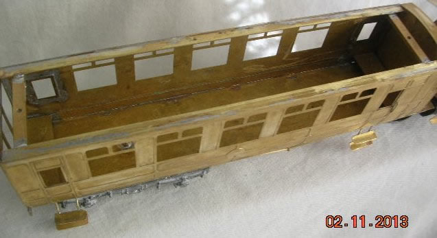
| Note the scrap brass strip soldered 1mm from the top to strengthen the sides and support the wooden roof which is held in place by 2 wood screws passed throught the drilled cross pieces and accessed through holes in the floor. | |
|
|
Reference Material: Building Model Locomotives by FJ Roche |
|